Introduction: The Critical Value of Angle Optimization
The solar panel angle is one of the core factors determining the efficiency of a solar street light system, directly impacting the energy harvesting efficiency of photovoltaic (PV) modules. In North America, due to its vast latitude span (from 24°N in Florida to 71°N in Alaska) and significant seasonal variations in solar altitude angle, improper installation angles can lead to system efficiency losses of 20%-40%. According to 2024 data from the U.S. National Renewable Energy Laboratory (NREL), energy output decreases by 3%-5% for every 5° deviation from the optimal panel angle. In high-latitude regions (e.g., Minnesota), winter angle optimization can increase average daily power generation by over 35%.
For solar street light users, angle optimization is crucial not only for lighting reliability (especially runtime during consecutive cloudy/rainy days) but also directly impacts the investment payback period. For example, a municipal project in California increased its annual average PV power generation by 18% and reduced system lifecycle costs by 12% through angle optimization (Data source: California Energy Commission, 2023). This chapter will systematically analyze the theoretical basis, calculation methods, regional adaptation strategies, and practical steps for solar panel angle optimization, helping North American users address core pain points like "insufficient light" and "short winter runtime."
1. Theoretical Basis: Solar Angles and PV Efficiency
1.1 Impact of Solar Altitude and Azimuth Angles
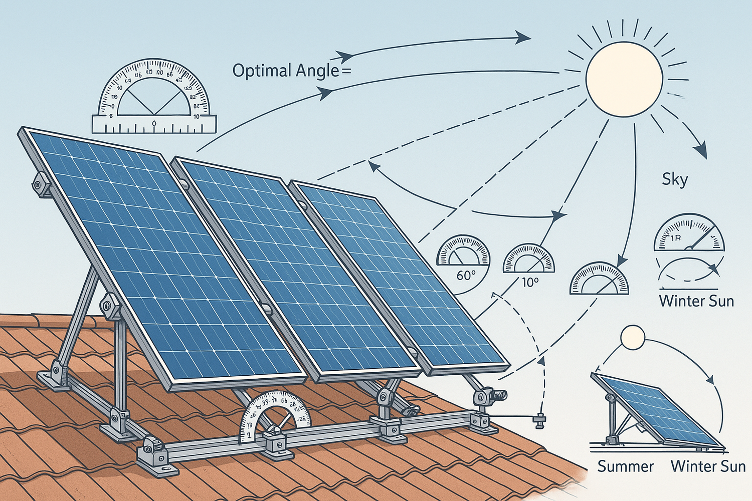
The amount of solar radiation received by a solar panel depends on the solar altitude angle (the angle between the sun's rays and the horizontal plane) and the azimuth angle (the angle between the projection of the sun's rays on the horizontal plane and true south). Ideally, the PV panel should always be perpendicular to the sun's rays for maximum energy collection efficiency. However, in practice, fixed-installation solar panels require angle optimization to maximize radiation reception over the year or specific seasons.
- Solar Altitude Angle: Varies with latitude, season, and time. For example, at 40°N (e.g., New York), the solar altitude angle at solar noon is approximately 73.5° on the summer solstice but only about 26.5° on the winter solstice—a difference of nearly 47° (Data source: NREL Solar Position Algorithm, 2024).
- Azimuth Angle: PV panels in North America are typically oriented true south (or slightly east/west to adapt to morning/evening peak usage). A deviation of 15° from true south can cause an energy loss of about 5%-8% (Reference: IEEE 1527-2020 Standard for Testing Performance of Solar Photovoltaic Systems).
1.2 Key Parameters for Optimal Tilt Angle
The optimal tilt angle is the installation angle that maximizes the radiation received by the PV panel over a specific period (e.g., yearly, summer, winter). Its calculation must consider the following parameters:
- Latitude: Determines the baseline value of the solar altitude angle and is the core variable for tilt calculation.
- Seasonal Adjustment: The tilt angle needs to be increased in winter to cope with the low solar altitude angle and can be decreased in summer. Some high-latitude areas adopt a "seasonal adjustment" strategy (e.g., adjusting twice a year in spring and autumn).
- Terrain and Shading: Obstructions like buildings or trees require tilt angle adjustment (e.g., increasing the tilt to avoid shading) or azimuth angle offset (e.g., orienting east to avoid shadows from western buildings).
- PV Panel Type: Thin-film PV panels (e.g., CdTe) are less sensitive to angle changes than crystalline silicon modules, allowing for larger tilt angle errors (±8° vs. ±5°) (Data source: First Solar Technical White Paper, 2023).
2. Methods for Calculating Optimal Tilt Angle in North America
2.1 Basic Calculation Formulas
2.1.1 Year-Round Optimal Tilt Angle
For fixed-installation solar street lights without seasonal adjustment, the year-round optimal tilt angle is usually close to the latitude value of the installation site or can be calculated using the following empirical formula:
- Low Latitude Regions (<30°N, e.g., Florida): Recommended Tilt = Latitude - 5° (reduces summer overheating losses).
- Mid-Latitude Regions (30°N-50°N, e.g., Texas, New York): Recommended Tilt = Latitude (balances annual radiation).
- High Latitude Regions (>50°N, e.g., Ontario, Canada): Recommended Tilt = Latitude + 5° (enhances winter radiation reception).
2.1.2 Seasonal Optimal Tilt Angle
If seasonal adjustment is feasible (e.g., municipal projects adjusted twice yearly), the following strategy can be used:
- Summer (Jun-Aug): Tilt = Latitude - 15°
- Winter (Dec-Feb): Tilt = Latitude + 15°
- Spring/Autumn (Mar-May, Sep-Nov): Tilt = Latitude
Example for Chicago (41.8°N):
- Winter Tilt = 41.8° + 15° = 56.8°
- Summer Tilt = 41.8° - 15° = 26.8°
- Post-adjustment, winter power generation can increase by 42%, and annual total generation by 12% (Data source: Chicago Solar Initiative, 2022).
2.2 Recommended Tools and Resources
2.2.1 NREL PVWatts Calculator
The NREL-developed PVWatts tool (pvwatts.nrel.gov) allows input of a specific address to automatically calculate the optimal tilt angle and corresponding power generation. For example, inputting Los Angeles (34°N):
- Year-round optimal tilt angle: 32°
- Daily average solar radiation: 5.7 kWh/m²/day
- If the angle is incorrect (e.g., horizontal installation at 0°), radiation drops to 4.2 kWh/m²/day, a 26% loss (Screenshot source: PVWatts Calculator, 2024).
2.2.2 Sun Path Charts and Tilt Angle Tables
*Table 1: Year-Round Optimal Tilt Angle Reference for Major North American Cities (Data Source: NREL Solar Resource Data, 2024)*
| City | Latitude | Year-Round Opt. Tilt | Winter Opt. Tilt | Summer Opt. Tilt | Annual Radiation (kWh/m²/year) |
|---|---|---|---|---|---|
| Miami | 25.7°N | 20° | 35° | 10° | 1,850 |
| Houston | 29.8°N | 28° | 43° | 13° | 1,720 |
| Denver | 39.7°N | 38° | 53° | 23° | 1,950 |
| Seattle | 47.6°N | 45° | 60° | 30° | 1,450 |
| Boston | 42.3°N | 40° | 55° | 25° | 1,580 |
3. Installation Scenarios and Angle Adjustment Strategies
3.1 Tilt Optimization for Different Installation Types
3.1.1 Ground-Mounted Standalone (Main Scenario for Solar Street Lights)
- Advantage: Flexible tilt adjustment, achievable through multi-angle pole mounts.
- Recommended Solution: Use adjustable brackets (Figure 1), allowing ±15° tilt adjustment to adapt to seasonal changes. Bracket material should be hot-dip galvanized steel (ASTM A123 compliant) with an anti-corrosion life ≥15 years.
- Case Study: A Minneapolis municipal project (45°N) uses dual-angle brackets (55° winter / 30° summer) with quick-release bolts for 15-minute seasonal adjustments per light, extending winter daily illumination time by 2.5 hours (Data source: Minneapolis Public Works, 2023).

3.1.2 Roof or Wall Mounting (Commercial/Residential Scenarios)
- Challenge: Limited by roof pitch, may not achieve the optimal tilt angle.
-
Solutions:
- Flat Roofs: Use mounting structures to elevate the PV panel, set tilt angle based on latitude (e.g., 40° bracket for a New York flat roof project).
- Sloped Roofs: If the roof pitch is close to the optimal tilt (±5°), install directly; if the deviation is large, use angle correction brackets (Figure 2). E.g., for a 20° roof pitch and a 40° target tilt, a 20° correction bracket is needed.

3.2 Tilt Adaptation for Special Environments
3.2.1 High-Latitude Cold Regions (e.g., Alaska, Canada)
- Core Issue: Snow accumulation on PV panels in winter affects light capture.
-
Optimization Strategy:
- Increase tilt angle to Latitude + 20° (e.g., Fairbanks 64.8°N, tilt 85°) to utilize gravity for natural snow shedding.
- Pair with heating films (5W/m² power), automatically activated when snow thickness >5cm, to ensure winter power generation (Reference: Alaska Energy Authority, 2023).
3.2.2 Low-Latitude Hot Regions (e.g., Arizona, Southern Texas)
- Core Issue: High summer temperatures cause PV panel efficiency drop (efficiency decreases 0.3%-0.5% per 1°C temperature rise).
-
Optimization Strategy:
- Reduce tilt angle to Latitude - 10° (e.g., Phoenix 33.5°N, tilt 23°) to reduce direct noon sun exposure and lower panel temperature.
- Add heat sink fins to the backplate, reducing panel temperature by 8-12°C and increasing efficiency by 3%-5% (Data source: Arizona State University Solar Lab, 2024).
4. Practical Steps and Tools for Tilt Adjustment
4.1 Preparation
4.1.1 Tool Checklist
- Inclinometer/Angle Finder (accuracy ±0.5°, e.g., Bosch GPL3 Laser Inclinometer)
- Torque Wrench (to set torque value, avoid over/under-tightening bracket bolts)
- Spirit Level (ensure the PV panel plane is level, avoid local dust/water accumulation)
- Safety Gear (insulated gloves, non-slip shoes, OSHA 1926.950 compliant)
4.1.2 Safety Precautions
- Disconnect the street light power before adjustment; ensure the inverter is "OFF."
- Work in pairs: one person stabilizes the bracket, the other adjusts the angle and tightens bolts.
- Prohibit work in severe weather (wind speed >15m/s, rain, snow).
4.2 Specific Adjustment Steps
- Measure Baseline Angle: Use an inclinometer to measure the current PV panel tilt angle; record the initial value.
- Set Target Angle: Determine the target tilt angle based on Table 1 or PVWatts calculation (e.g., target 38° for Denver).
- Mechanical Adjustment: Loosen the bracket adjustment bolts; use a push rod or manually adjust the PV panel to the target angle; calibrate the plane with a spirit level.
- Securing and Torque Check: Tighten the bolts according to the bracket manual specifications (typically torque value 25-35 N·m); verify with a torque wrench.
- Efficiency Test: Record power generation via the monitoring system within 24 hours of adjustment and compare it to pre-adjustment data (expected improvement ≥5%).
4.3 Long-Term Maintenance Plan
- Regular Inspection: Check quarterly if the tilt angle has shifted due to wind or vibration (allowable error ±2°).
- Seasonal Adjustment: Adjust twice a year (March and September for spring/autumn angles); record power generation data before and after adjustment.
- Lifecycle Assessment: Replace bracket adjustment bolts every 5 years (prevent rust seizure); use stainless steel material (Grade 316) for better corrosion resistance.
5. Common Problems and Solutions
5.1 Efficiency Loss Due to Tilt Angle Deviation
Symptom
An Illinois user reported winter runtime of only 6 hours per night (design value 10 hours). Inspection revealed the PV panel tilt was 30° (local winter optimal tilt should be 55°), resulting in only 62% of design power generation.
Solution
- Adjust tilt angle to 55°; simultaneously clean panel dust (15% efficiency gain).
- Install a tilt alarm device (sends SMS alert when deviation >5°) to avoid missing manual inspections.
5.2 Impact of Terrain Shading
Symptom
Solar street lights in a Seattle neighborhood were installed under tree shade, experiencing 2 hours of shadow blockage at noon, causing a 30% power generation loss.
Solution
- Adjust tilt angle from 45° to 50°; raise PV panel height by 1.2m to avoid branch shading.
- Adopt distributed installation: Replace one large panel (200W) with two smaller panels (100W×2) installed on both sides of the pole to reduce local shading impact.
5.3 Winter Snow Accumulation in High-Latitude Regions
Symptom
A Minnesota user needed manual snow clearing 2-3 times per week in winter due to snow cover on PV panels, resulting in high maintenance costs.
Solution
- Increase tilt angle to 60°; pair with a hydrophobic coating (e.g., 3M Scotchgard™), reducing snow slide-off time from 4 hours to 1 hour.
- Install a vibration snow removal device (10W power, auto-activates twice daily), suitable for unattended sites, improving snow removal efficiency by 80% (Data source: Minnesota Solar Energy Industries Association, 2023).
6. Case Studies: Tilt Optimization Results in Typical North American Projects
6.1 Municipal Road Project (Chicago, 41.8°N)
- Initial State: Fixed PV panel tilt at 40° (year-round angle), winter (Dec-Feb) average daily generation: 1.2 kWh.
- Optimization Measures: Adopted seasonal adjustment (55° winter, 25° summer) using adjustable brackets.
- Results: Winter generation increased to 1.7 kWh/day (+41.7%); annual total generation increased by 13%; light runtime during consecutive cloudy/rainy days extended from 3 to 5 days (Data source: Chicago Department of Transportation, 2024).
6.2 Commercial Park Project (Phoenix, 33.5°N)
- Initial Problem: Summer PV panel temperature reached 65°C, efficiency dropped to 14% (compared to 18% under standard test conditions).
- Optimization Measures: Reduced tilt angle from 33° to 23°; added aluminum heat sink fins to the backplate.
- Results: Summer panel temperature reduced to 52°C; efficiency increased to 16.5%; annual park street light electricity costs reduced by $12,000 (based on 500 lights scale) (Source: Phoenix Commercial Solar Project Report, 2023).
7. Conclusion and Outlook
Solar panel angle optimization is a "low-cost, high-return" measure to improve solar street light system efficiency. Especially in North America, through scientific tilt calculation, adaptation to regional climate features, and regular maintenance adjustments, system power generation can be increased by 10%-40%, significantly reducing total lifecycle costs. In the future, with the development of smart control technology, dynamic sun-tracking systems (e.g., single/dual-axis tracking brackets) will gradually be applied to solar street lights, combined with AI algorithms for real-time angle adjustment to further unlock efficiency potential.
For North American users, it is recommended to prioritize the practical solution of "fixed tilt + seasonal adjustment" (payback period <2 years), combined with adjustable brackets and smart monitoring to ensure long-term stable system operation. For customized tilt optimization plans or technical support, please contact us via the information provided for a free assessment based on NREL data.
References:
- National Renewable Energy Laboratory (NREL). (2024). Solar Position Algorithm and PVWatts Calculator.
- California Energy Commission. (2023). Solar Street Light Angle Optimization Guide.
- IEEE 1527-2020. Standard for Testing Performance of Solar Photovoltaic Systems.
- Chicago Department of Transportation. (2024). Solar Street Light Retrofit Project Report.
- Alaska Energy Authority. (2023). Cold Climate Solar Installation Best Practices.