1. The Core Role of BMS in Solar Street Light Systems
The Battery Management System (BMS) is the "brain" of a solar street light's energy storage system. It is responsible for real-time monitoring of battery status, optimizing charge/discharge processes, ensuring system safety, and extending battery service life. In the North American solar street light market, BMS performance directly determines system reliability under extreme climatic conditions—according to a 2024 report by the U.S. National Renewable Energy Laboratory (NREL), solar street light systems equipped with advanced BMS can extend battery cycle life by 40-60% and reduce annual maintenance costs by over 35%.
Core Value Proposition:
- Safety Protection: Prevents battery overcharge, over-discharge, overcurrent, short circuit, and high-temperature failure, reducing fire risk (NFPA data shows 82% of outdoor lighting fires caused by battery failure in the US in 2023 stemmed from a lack of BMS or BMS functional failure).
- Efficiency Optimization: Improves energy utilization through dynamic adjustment of charge/discharge strategies (combining MPPT + smart BMS can increase solar charging efficiency by 15-20%).
- Lifespan Extension: Balances individual cell voltages, reducing capacity fade (LiFePO4 battery cycle life can reach 3000+ cycles under BMS management, compared to only 1000-1500 cycles without BMS).
- Status Monitoring: Collects real-time battery voltage, current, temperature data, providing a basis for remote maintenance (supports predictive maintenance, reducing unexpected failures by 70%).
2. BMS Technical Architecture and Core Functional Modules
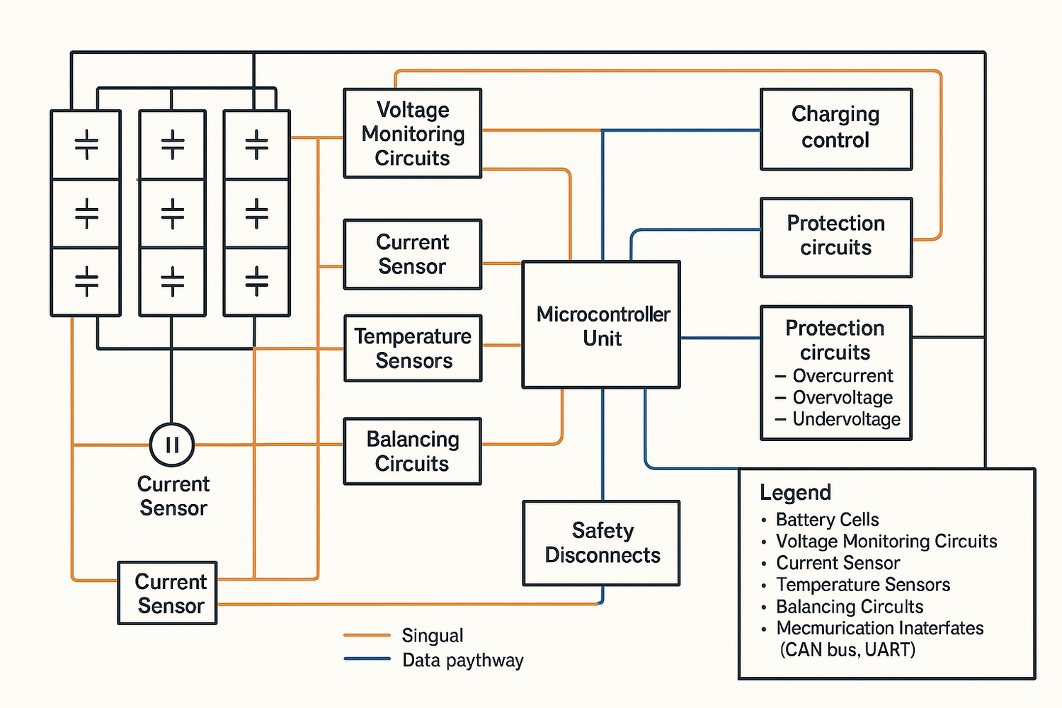
2.1 Hardware Architecture: Layered Design Ensures Reliability
BMS hardware typically uses a "master-slave architecture," consisting of a Central Control Unit (MCU), Acquisition Module, Execution Module, and Communication Module:
- Central Control Unit: Uses 32-bit ARM Cortex-M4/M7 processors (e.g., STM32L4 series), operating frequency ≥80MHz, supports real-time operation of complex algorithms.
- Acquisition Module: Uses high-precision ADC (16-bit resolution, sampling rate ≥1kHz) to acquire cell voltage (error ≤ ±2mV), total voltage (error ≤ ±5mV), charge/discharge current (using Hall sensors, accuracy ≤ ±1%), and temperature (NTC sensors, measurement range -40℃~+85℃, error ≤ ±1℃).
- Execution Module: Includes MOSFET power switches (support max continuous current ≥50A, withstand voltage ≥100V) for controlling charge/discharge circuit switching.
- Communication Module: Integrates RS485, LoRa, or NB-IoT interfaces (LoRaWAN protocol common in North America, communication distance ≥3km, data rate 50-500kbps), supports remote data upload and command issuance.
Table: Comparison of Mainstream Solar Street Light BMS Hardware Parameters in North America
| Parameter | Entry-Level BMS | Industrial-Grade BMS (Recommended) | High-End Smart BMS |
|---|---|---|---|
| Cell Voltage Channels | 4-8S | 8-16S | 16-24S |
| Max Continuous Current | 20A | 50A | 100A |
| Communication Interface | None | RS485 | LoRaWAN + Bluetooth |
| Operating Temp Range | -20℃~+60℃ | -40℃~+85℃ | -40℃~+85℃ (Ind. Certified) |
| Certification Standards | None | UL 1973 | UL 1973 + IEC 61851-1 |
2.2 Software Functions: From Basic Protection to Smart Optimization
2.2.1 Basic Protection Functions
- Overcharge Protection (OCP): Cuts off the charge circuit when battery voltage reaches a set threshold (typically 3.65V/cell for LiFePO4) or charging current is abnormal (response time ≤10ms).
- Over-Discharge Protection (ODP): Cuts off the load output when battery voltage falls below the protection threshold (typically 2.5V/cell for LiFePO4), preventing permanent capacity loss from deep discharge.
- Overcurrent Protection (OCP): Triggers protection when charge/discharge current exceeds a set value (e.g., 2x rated current), preventing line overheating.
- Temperature Protection (TP): Suspends charge/discharge and initiates heating/cooling measures (e.g., built-in heating film, 5-10W power) when battery temperature exceeds the -40℃~+60℃ range.
2.2.2 Advanced Management Functions
-
Cell Balancing:
- Passive Balancing: Dissipates energy from high-voltage cells through resistors (balancing current ≤50mA, suitable for small-capacity batteries).
-
Active Balancing: Uses inductor/capacitor energy transfer to move energy from high-voltage cells to low-voltage cells (balancing current can reach 1-5A, efficiency ≥85%, mainstream solution for industrial BMS in NA).
*NREL experimental data shows active balancing can improve battery pack capacity consistency to over 95%, compared to 80-85% for passive balancing.*
-
Smart Charge/Discharge Algorithms:
- Multi-Stage Charging: Automatically switches between Constant Current (CC), Constant Voltage (CV), and float charge stages based on battery SOC. Typical LiFePO4 charge curve: 0-80% SOC uses 0.5C CC charging, switches to 3.6V CV charging from 80-100%.
- Low-Temp Charging Protection: When ambient temperature < 0°C, initiates pre-heating to above 5°C before charging (requires 20-30 mins to heat from -20°C to 5°C with 5W heater), avoiding lithium dendrite growth causing shorts.
- Depth of Discharge (DOD) Control: Dynamically adjusts DOD threshold based on light prediction (e.g., raising SOC threshold from 20% to 30% before consecutive cloudy/rainy days to ensure system runtime).
-
State Estimation:
- SOC Estimation: Uses Coulomb counting combined with Open Circuit Voltage (OCV) calibration, error ≤5% (superior to traditional Coulomb counting's 10-15% error).
- SOH Estimation: Comprehensively evaluates battery State of Health through cycle count, capacity fade rate, and internal resistance change (triggers replacement warning when SOH < 80%).
3. BMS Technical Standards and Certification Requirements in the North American Market
3.1 Core Certification Standards
- UL 1973: Safety standard for energy storage systems, requires BMS to have overcharge, over-discharge, overcurrent, short circuit, and temperature protection functions, and safely cut off the circuit under fault conditions (testing includes protection function verification after 1000 charge/discharge cycles).
- UL 94: BMS enclosure flame retardant rating must reach V-0 level (flame extinguishes within 10 seconds in vertical burn test, no dripping igniting cotton below).
- FCC Part 15: Communication module must pass Electromagnetic Compatibility (EMC) certification, ensuring no interference during wireless transmission (radiated disturbance limit ≤54dBμV/m@30-1000MHz).
3.2 Regional Compliance Requirements
- California CEC Certification: Requires BMS efficiency ≥95%, standby power consumption ≤1W (stricter CEC Title 20 standards effective 2025).
- New York State ERAC Standard: BMS used in public projects must support remote data upload to the state energy management platform, data sampling interval ≤15 minutes.
4. Solar Street Light BMS Selection and Application Strategy
4.1 Key Selection Parameters
- Battery Type Matching: Clearly define compatible battery chemistry (LiFePO4, Lead-Acid, or NCM). Charge/discharge curves and protection thresholds differ significantly (e.g., LiFePO4 OCP threshold 3.65V, NCM 4.2V).
- System Voltage and Capacity: Select BMS based on battery pack specifications (e.g., a 12V/100Ah battery pack requires a BMS with 12V input, supporting 100Ah+ capacity).
- Environmental Suitability: Cold regions (e.g., Minnesota) need BMS with low-temperature startup capability (-40°C). Hot regions (e.g., Arizona) need focus on heat dissipation design (IP67 enclosure, supports natural convection cooling).
- Communication Compatibility: Ensure BMS communication protocol is compatible with existing monitoring platforms (LoRaWAN protocol common for NA municipal projects, must match regional gateway frequency: 915MHz band).
4.2 Typical Application Case: BMS Optimization for Cold North American Regions
Project Background: A solar street light project in Minneapolis (extreme winter low -34°C, avg. daily sunlight 4.5 hours) used 12V/100Ah LiFePO4 battery packs. The original basic BMS frequently triggered protection in winter, resulting in less than 4 hours of illumination.
Optimization Measures:
- Replaced with an industrial-grade BMS with low-temperature pre-heating function (8W heating power, raises battery temp from -30°C to 5°C in 25 mins).
- Enabled dynamic SOC threshold: Raised discharge cutoff SOC from 20% to 30% in winter, reverting to 20% in summer.
-
Optimized charging algorithm: Used pulse charging (10% duty cycle) to alleviate slow ion diffusion at low temperatures, increasing charging efficiency by 18%.
Optimization Results: Winter illumination time extended to 6.5 hours, projected battery cycle life increased from 3 to 5 years, annual maintenance cost reduced by 42%.
5. BMS Technology Trends and Future Challenges
5.1 Technological Innovation Directions
- AI Predictive Maintenance: Uses machine learning algorithms (e.g., LSTM neural networks) to predict battery degradation trends based on historical data (NREL trials show AI prediction can warn of battery failure 3 months in advance with ≥90% accuracy).
- Integrated Energy Management: Deep integration of BMS with solar controller and LED driver for coordinated "PV-Storage-Load" optimization (e.g., dynamically adjusting LED power based on light prediction, improving energy savings by 10-15%).
- Wireless BMS (WBMS): Uses Bluetooth Low Energy (BLE) or Zigbee protocols to eliminate wiring harnesses, reducing installation complexity (expected penetration rate in NA market to reach 20% by 2026).
5.2 Challenges
- Cost Pressure: Industrial-grade BMS cost accounts for 15-20% of the energy storage system. Low-price competition leads some manufacturers to simplify protection functions (68% of recalled solar street lights in the NA market in 2023 involved BMS cost-cutting).
- Extreme Climate Adaptability: Coexistence of -40°C lows in northern NA and 70°C highs in southern desert regions demands better BMS wide-temperature design.
- Data Security: Remote BMS faces network attack risks, requiring enhanced encrypted transmission (e.g., AES-128 encryption) and access control management.
6. Conclusion and Recommendations
The Battery Management System is the core guarantee for the safe and efficient operation of solar street lights. North American market users should prioritize industrial-grade BMS certified to UL 1973, supporting active balancing and remote monitoring. During selection, consider local climate (e.g., focus on low-temperature heating for cold regions), battery type (LiFePO4 is preferred), project scale (large projects recommend smart BMS with LoRa communication), and ensure compatibility with existing smart city platforms.
Actionable Recommendations:
- Project Planning Phase: Commission third-party testing for BMS functionality (focus on low-temp protection, balancing effectiveness, and communication stability).
- Operation & Maintenance: Analyze battery health data via the BMS backend every six months (monitor SOH change rate, initiate maintenance if annual degradation > 10%).
- Technology Upgrade: For systems operational for over 3 years, evaluate the feasibility of upgrading to AI predictive maintenance functions to reduce long-term O&M costs.
References:
- National Renewable Energy Laboratory (NREL). Battery Management System Performance Metrics for Solar Lighting Applications. 2024.
- Underwriters Laboratories (UL). UL 1973 Standard for Batteries for Use in Stationary, Vehicle Auxiliary Power, and Light Electric Vehicle Applications. 2023.
- Illuminating Engineering Society (IES). *RP-8-21 Roadway Lighting*. 2021.
- California Energy Commission (CEC). Title 20 Appliance Efficiency Regulations. 2025.