Introduction: The Core Value of Power Matching
Enhancing the energy efficiency and ensuring the reliability of solar street light systems fundamentally depend on the precise regulation of power flow – the dynamic balance between the energy output of the photovoltaic (PV) modules, the charge/discharge capability of the energy storage system, and the actual demand of the load. In the US market, power mismatch is a primary technical pain point leading to system inefficiency and reduced battery lifespan. According to a 2024 US Department of Energy (DOE) report, approximately 25% of PV energy is wasted due to power mismatch in unoptimized systems, directly resulting in winter lighting duration being shortened by over 30%.
The commercial value of power optimization is equally significant: precise matching technology can reduce PV module configuration capacity by 15-20%, lowering initial investment costs. Concurrently, battery cycle life can be extended by 40%, reducing total lifecycle maintenance costs by 50%. For North American municipal projects, this means maintaining project economics through technical optimization even as federal tax credit policies tighten (scheduled to terminate at the end of 2025).
This chapter will systematically analyze the technical principles of solar street light power matching, component sizing methodologies, dynamic management strategies, and North American compliance requirements, providing actionable optimization solutions for diverse application scenarios.
1. Core Principles and Technical Challenges of Power Matching
1.1 The Triangular Power Flow Balance Model
The power flow within a solar street light system involves three core components; their dynamic matching forms the foundation for efficient operation:
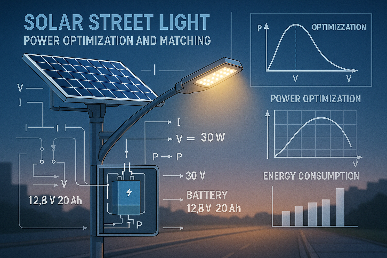
- Photovoltaic Power Output (P_PV): Influenced by irradiance, temperature, shading, etc., exhibiting non-linear characteristics with a Maximum Power Point (MPP), requiring real-time tracking via an MPPT controller.
- Energy Storage System Power Buffering (P_BAT): Responsible for energy storage and release, with its charge/discharge power constrained by battery State of Charge (SOC), temperature, and cycle life limitations.
- Load Power Demand (P_LOAD): Includes the base lighting power (LED luminaire) and additional functional power (e.g., sensors, communication modules), requiring dynamic adjustment based on the scenario.
The balance relationship between these three can be expressed as:P_PV(t) = P_BAT_charge(t) + P_LOAD(t) - P_BAT_discharge(t)
During sufficient sunlight (P_PV > P_LOAD), excess energy charges the battery. During insufficient sunlight (P_PV < P_LOAD), the battery discharges to supplement the deficit. Imbalance in matching leads to energy waste at best, and severe cases can cause battery overcharge/over-discharge or load power failure.
1.2 Key Technical Challenges
The diversity of North American climates and application scenarios intensifies power matching difficulty. Primary challenges include:
- Irradiance Fluctuation: Midwestern US summer noon irradiance can reach 1000 W/m², while winter cloudy days may see only 100 W/m² – a 10-fold power fluctuation requiring rapid response mechanisms.
- Temperature Sensitivity: PV module power temperature coefficient is approximately -0.34%/°C. Under Arizona summer high temperatures, power output can drop by 15%. Lithium battery capacity at -20°C can be only 60% of rated value, further exacerbating matching difficulty.
- Load Diversification: Smart street light add-ons (e.g., 5G micro-cells, EV charging points) increase load power from the traditional 50W to over 500W, with intermittent surges, necessitating dynamic priority allocation.
- Grid Compliance Requirements: Grid-connected solar street lights must comply with IEEE 1547.1 standards, requiring power regulation capability during voltage/frequency deviations to avoid grid impact.
2. Component Power Sizing and Matching Formulas
2.1 Photovoltaic Module Power Sizing
PV module power sizing is based on daily average peak sun hours (H_solar) and daily load energy consumption (E_load). The core formula is:P_PV = E_load / (H_solar × η_system)
- E_load: Daily load energy consumption (Wh). Example: 100W LED operating 10 hours/day = 1000 Wh.
- H_solar: Local daily average peak sun hours. Southwestern US (e.g., AZ) ≈ 6.5 hrs, Northeastern US (e.g., ME) ≈ 3.5 hrs (Source: NREL Solar Resource Data).
- η_system: Total system efficiency, including PV conversion efficiency (~15-22%), MPPT efficiency (~95-99%), and wiring losses (~5%). Composite efficiency η_system ≈ 0.15 × 0.97 × 0.95 ≈ 0.137 (using monocrystalline silicon as an example).
Case Calculation:
Location: Los Angeles, CA (H_solar=5.5 hrs). Load: 100W LED (10 hrs/day).E_load = 100W × 10h = 1000 WhP_PV = 1000 Wh / (5.5h × 0.137) ≈ 135 W
Therefore, size a 150W PV module (including 10% redundancy).
2.2 Energy Storage Battery Capacity Matching
Battery capacity must meet power demand during consecutive backup days (D_backup). Formula:C_BAT = (E_load × D_backup) / (U_BAT × DOD)
- D_backup: Design backup days (e.g., 5 days for rainy WA, 3 days for arid NV).
- U_BAT: Battery nominal voltage (e.g., 12V).
- DOD: Depth of Discharge threshold (Lithium typically 80%, Lead-acid typically 50%).
Case Calculation:
Continuing LA case. Use 12V Li-ion (DOD=80%), Design backup days=5.C_BAT = (1000 Wh × 5) / (12V × 0.8) ≈ 520 Ah
Therefore, configure 4 x 130 Ah Li-ion batteries (12V series connection).
2.3 Controller Power Matching
The controller must match both PV max power (P_PV_max) and load max current (I_load_max). Sizing formulas:P_controller ≥ P_PV_maxI_controller ≥ I_load_max = P_load_max / U_system
- P_PV_max: PV module maximum power (e.g., 150W).
- P_load_max: Load maximum power (e.g., 100W base + 50W add-ons = 150W).
- U_system: System voltage (e.g., 12V).
Case Calculation:
System voltage=12V, Max load power=150W.I_load_max = 150W / 12V = 12.5 A
Therefore, select an MPPT controller ≥15A (e.g., 20A model for redundancy).
3. Dynamic Power Management Strategies
3.1 MPPT Algorithm Optimization
Maximum Power Point Tracking (MPPT) is the core technology for PV power optimization. Performance comparison of different algorithms:
| Algorithm Type | Efficiency | Response Speed | Complexity | Ideal Application Scenario |
|---|---|---|---|---|
| Perturb & Observe (P&O) | 95-98% | Medium (100ms) | Low | Stable irradiance regions (e.g., Florida) |
| Incremental Conductance (INC) | 96-99% | Fast (50ms) | Medium | High irradiance fluctuation (e.g., Texas) |
| Fuzzy Logic Control | 97-99.5% | Very Fast (20ms) | High | Complex load scenarios (e.g., Smart City) |
North American Application Recommendations:
- Midwest (Sunny): Prioritize P&O (cost-effective, stable) - e.g., SolarEdge SE3500.
- Northeast (Cloudy): Use INC (fast cloud response) - e.g., Morningstar TriStar.
- Smart City Projects: Fuzzy Logic Control (adapts to dynamic loads) - e.g., Schneider Conext XW Pro.
3.2 Temperature Compensation Strategy
The impact of temperature on power requires correction via dynamic parameter compensation. Key measures:
- PV Side: Real-time module temperature sensing to adjust MPPT voltage thresholds. Example: Monocrystalline module MPP voltage at 25°C is 36V; voltage decreases ~0.34V per 10°C rise, requiring controller dynamic adjustment.
- Battery Side: Low temps (<0°C): Reduce charge current to 50% of rated value to prevent lithium plating. High temps (>45°C): Activate cooling fans and reduce charge termination voltage (e.g., from 14.4V to 13.8V).
Case Study: Minnesota winter (-20°C): A solar street light using temperature compensation increased battery charge efficiency from 60% to 85%, extending lighting duration by 3 hours (Source: University of Minnesota Energy Research Center, 2024).
3.3 Hybrid Load Priority Management
During power deficit, energy must be allocated by priority. Typical priority ranking:
| Load Type | Priority | Power Share | Regulation Strategy |
|---|---|---|---|
| Emergency Lighting | 1 (High) | 30% | Maintain minimum illuminance (5 lux) |
| Traffic Camera | 2 | 20% | Reduce frame rate (15fps → 10fps) |
| Environmental Sensors | 3 | 10% | Increase sampling interval (1min → 5min) |
| 5G Micro-cell | 4 (Low) | 40% | Turn off during off-peak hours (00:00-06:00) |
Implementation: Use the smart controller's programmable logic (e.g., Modbus protocol) to monitor battery SOC in real-time. Sequentially disconnect lower-priority loads when SOC < 30%.
4. North American Compliance and Testing Standards
4.1 IEEE 1547 Distributed Energy Resources Standard
Grid-connected solar street lights must meet IEEE 1547.1-2020 power regulation requirements:
- Voltage Response: For ±5% voltage deviation, power regulation rate ≤ 10% rated power/second.
- Frequency Response: For frequency deviation ±0.5Hz from 60Hz, cease export within 2 seconds.
- Fault Ride-Through (FRT): Maintain connection for ≥150ms during voltage sags to 0% (Low Voltage Ride-Through, LVRT).
4.2 UL Safety Certification (UL 1741)
Key UL 1741 requirements for power conversion equipment:
- Overcurrent Protection: Output short circuit must be disconnected within 100ms.
- Insulation Resistance: ≥100MΩ between input and output (tested at 500V DC).
- Temperature Limits: Power device surface temperature ≤90°C (at 25°C ambient).
4.3 Testing Procedures (Example: CEC Efficiency Certification)
Steps include:
- Standard Test Conditions (STC): 25°C, 1000 W/m², AM1.5 spectrum - measure MPP power.
- Low-Light Performance Test: Efficiency at 200 W/m² (must be ≥ 90% of STC efficiency).
- Temperature Coefficient Test: Power variation curve from -10°C to +50°C.
- Dynamic Response Test: Simulate cloud transients (1000→200→1000 W/m²) - record MPPT tracking time (must be <1 second).
5. Regional Power Configuration Case Studies
5.1 Arizona (High Temperature, High Irradiance Zone)
- Scenario: Phoenix municipal roadway (H_solar=6.5 hrs, summer extreme temp 45°C).
-
Configuration:
- PV: 300W Monocrystalline (Temp Coeff -0.32%/°C), 20° tilt (winter optimization).
- Battery: 12V/200Ah LiFePO4 (Op. Temp -20°C to 60°C).
- Controller: 40A MPPT (Fuzzy Logic), with heatsink.
- Optimization: PV backsheet reflective coating (reduces temp 5-8°C), battery compartment insulation.
5.2 Washington (Rainy, Low Irradiance Zone)
- Scenario: Seattle park pathway (H_solar=3.5 hrs, annual rain 150 days).
-
Configuration:
- PV: 200W Polycrystalline (superior low-light response), 45° tilt (maximize winter gain).
- Battery: 24V/300Ah LiFePO4 (higher capacity for extended cloudy periods).
- Controller: 30A MPPT (INC Algorithm), with photocell + timer dual-mode.
- Optimization: PV anti-reflective coating (boosts low-light efficiency 3%), integrate small wind turbine (supplemental power).
5.3 New York (Mixed Climate, High-Demand Zone)
- Scenario: NYC smart street light (with 5G micro-cell, high load fluctuation).
-
Configuration:
- PV: 250W Bifacial (15% energy gain from dual-side generation).
- Battery: 48V/100Ah LiFePO4 (higher voltage reduces line losses).
- Controller: 60A Hybrid (PV + Grid inputs), supports remote power scheduling.
- Optimization: AI-based load forecasting (using NOAA weather data) for proactive energy storage strategy adjustment.
6. Conclusion and Future Trends
Power optimization and matching are core technologies for enhancing solar street light system efficiency, reliability, and economics, requiring synergistic efforts in component sizing, algorithm optimization, and dynamic management. The regional climate variations and stringent compliance requirements of the North American market further highlight the importance of customized solutions – from Arizona's high-temperature thermal management to Washington's low-light efficiency strategies, technical paths must be adapted locally.
Future Trends Include:
- AI Predictive Control: Combining machine learning with meteorological big data for highly accurate power demand forecasting (error <5%).
- Wide-Bandgap Semiconductor Adoption: SiC MOSFET controllers boosting conversion efficiency to 99.5%, reducing thermal losses.
- Distributed Storage Networking: Coordinated dispatch of multiple street light storage systems, forming Virtual Power Plants (VPPs) for grid peak shaving.
By implementing the technical solutions outlined in this chapter, North American users can optimize power configuration based on local conditions. Even amidst federal subsidy phase-outs, this enables project payback periods to be shortened by 1-2 years, laying the foundation for the widespread adoption of solar street lighting.
Sources Cited:
- National Renewable Energy Laboratory (NREL). Solar PV System Performance Analysis. 2024.
- IEEE 1547.1-2020. Standard for Inverters, Converters, Controllers and Interconnection System Equipment for Use With Distributed Energy Resources.
- California Energy Commission (CEC). Solar Equipment Efficiency Ratings. 2025.
- University of Minnesota. Cold Climate Solar PV Performance Optimization. 2024.
- DOE Municipal Solid-State Street Lighting Consortium. LED Street Light Power Management Guide. 2023.